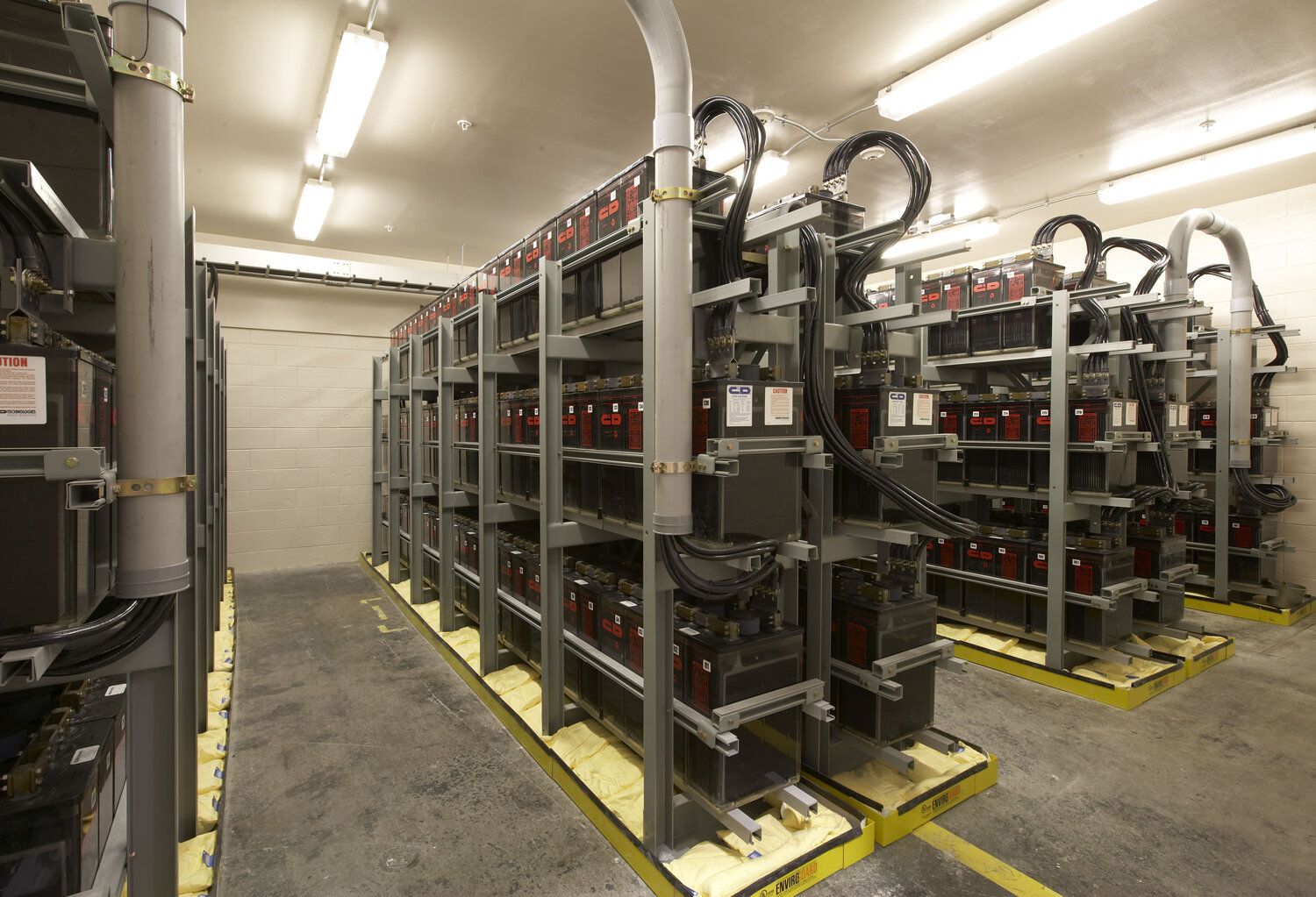

You might be familiar with the term “commissioning” especially if you work in the construction phase of a project. Normally, a constructor will do a commissioning test before handing over the Project to the project owner. This step states that the overall work that has been done by the constructor has already met the customer requirement and factory specification. In some countries, if an industry uses power sources from the utility, the utility will do an inspection first to declare that the electrical system is proper to operate so commissioning is very important.
A commissioning test in electrical systems involves a series of checks and tests performed on newly installed or upgraded electrical equipment to ensure it operates correctly and meets design specifications. The process verifies that all components function as intended and that the system can be safely and reliably brought into service.
Commissioning switchgear involves several types of testing and verification procedures to ensure that the equipment operates safely and efficiently within an electrical system. These commissioning activities can be broadly categorized into pre-commissioning tests, functional tests, and performance tests. Each type of commissioning has its specific objectives and methodologies, aimed at validating different aspects of the switchgear. Here are several types of commssioning test in a switchgear
1. Circuit Breaker Test
This test is conducted to verify the operation of the circuit breaker (CB) in both the open and close positions. It includes testing the manual operation of the CB as well as the automatic operation by sending a signal to the protection relay. This ensures that the CB can effectively interrupt and restore power as required under various conditions. Additionally, if a motorized circuit breaker is used, it is crucial to test the spring charging mechanism. This involves verifying that the motor correctly charges the closing spring, ensuring the circuit breaker is ready for subsequent operations. Proper functioning of both the manual and automated mechanisms, along with the spring charging system, is essential for the reliable performance of the circuit breaker in protecting electrical systems from faults.
2. Functional Test of Mechanical and Electrical Function
The functional testing of switchgear includes both mechanical and electrical aspects to ensure all safety and operational features work correctly. The mechanical function tests focus on verifying the interlocks between the circuit breaker and the earthing switch, ensuring that these components interact properly to prevent dangerous electrical conditions. Additionally, the interlock function between the earthing switch and the switchgear door is tested to confirm that the door cannot be opened unless the earthing switch is in a safe position. Other safety-related mechanical functions, such as the proper operation of handles, latches, and locking mechanisms, are also checked.
On the electrical side, the functional tests include verifying that all indicator lamps and other electrical components operate correctly. This ensures that the visual indicators provide accurate status information to operators, which is crucial for safe and efficient operation. Moreover, some switchgear systems incorporate electrical interlock mechanisms using a castle key system. This mechanism is designed to ensure that certain operations can only occur in a specific sequence, enhancing safety and preventing incorrect operations. Testing the castle key mechanism involves verifying that it functions exactly as designed, ensuring that the interlocks provide the intended protection and operational sequence.
3. CT and VT Test
Current Transformers (CTs) and Voltage Transformers (VTs) are essential components in electrical systems, serving critical roles in both protection and metering applications. These transformers ensure accurate measurement and safe operation by scaling down high currents and voltages to manageable levels for relays and meters. To verify their proper function, several tests are typically conducted on CTs and VTs. The primary injection test involves injecting a known primary current into the CT and measuring the corresponding secondary current to confirm the transformer’s accuracy and performance under load conditions. This test helps identify any deviations in the CT’s operation.
A ratio check is performed to ensure the CT or VT accurately transforms the primary current or voltage to the specified secondary value. This involves comparing the measured output to the expected output based on the transformer’s designed ratio, thus validating its accuracy. Polarity checks are conducted to verify the correct orientation of the transformer’s windings and connections. Ensuring proper polarity is crucial for the accurate operation of protection schemes and metering, as incorrect polarity can lead to faulty readings and malfunctioning protective devices.
Together, these tests confirm that the CTs and VTs function correctly and reliably, providing accurate measurements and ensuring the safety and efficiency of the electrical system.
4. Protection Relay Test
Protection relay testing involves several critical procedures to ensure the relay operates correctly and provides the necessary protection to the electrical system. One key aspect of this testing is the tripping test, where the relay is activated to simulate fault conditions, confirming that it can successfully initiate a trip command to disconnect the faulty section of the system. This verifies that the relay responds appropriately to actual fault scenarios, ensuring system safety and reliability.
Additionally, a secondary injection test is performed to assess the relay’s accuracy in reading voltage and current levels as they would occur in the system. During this test, known voltage and current signals are injected into the relay’s secondary terminals, and its response is observed. This helps determine if the relay correctly interprets these signals and triggers the appropriate protective actions. The secondary injection test is crucial for verifying the relay’s calibration and ensuring its settings are accurate, ultimately confirming that the relay will perform reliably under real-world conditions and provide accurate protection for the electrical system.
5. Contact Resistance Test
A contact resistance test is performed to measure the resistance at the interface of electrical connections, including circuit breaker contacts, switches, connectors, and busbars. This test is crucial for identifying any high-resistance connections that could lead to energy losses, overheating, or potential failure within the electrical system. By injecting a known current through the connection and measuring the resulting voltage drop, the resistance can be calculated using Ohm’s Law. Ensuring low contact resistance is vital for maintaining efficient and reliable electrical connections, preventing excessive power dissipation, and ensuring the longevity and safety of the equipment.
6. Megger and Hipot Test
The purpose of the Megger test, also known as an insulation resistance test, is to measure the insulation resistance of electrical equipment to ensure its integrity and reliability. This test typically involves measuring the resistance between two phases, as well as between each phase and ground. High insulation resistance indicates good insulation, which is essential for preventing electrical leaks and ensuring safe operation.
Following the Megger test, a High Potential (Hipot) test is conducted. The Hipot test aims to measure the discharge current within the switchgear to ensure it remains within acceptable limits. This test involves applying a high voltage to each phase of the switchgear while grounding the remaining phases to ensure safety. The discharge current measured during this test helps identify any weaknesses or potential breakdowns in the insulation.
For safety, it is crucial to discharge any stored current to the ground after the Hipot test. This step is necessary to protect personnel from potential electric shock hazards. Ensuring the proper discharge of current also helps maintain a safe working environment and confirms that the equipment is safe for continued operation.
By systematically executing these tests, engineers can confirm that the switchgear meets design specifications, regulatory standards, and operational requirements, ultimately ensuring reliable and safe power distribution.
